38-9 Restoration

Home Up The Story Feedback               
Home
The Beginning
Don't Plug it In
8.  Triage Problems
The Plan

 1.  Get the Data

 2.  Block Diagram

 3.  Pre-Flight Checks

 4.  What Needs Replacement?

 5.  Ordering Parts

 6.  Install Electrolytics

 7.  First Power-On Checks

 8.  Triage Problems - more trouble!

 9.  Complete Electrical Restoration

10.  2nd Pre-Flight and Power-On, and The Last Problem

Additional Resources

 o  Antenna in the attic

 o  Shortwave Listening Guide

 o  Philco and Radio History

 o  Other Links


At this point, with the major caps replaced, and all of the obvious issues cleaned up, I should have had better results.  But the set remained essentially quiet.

Full Power
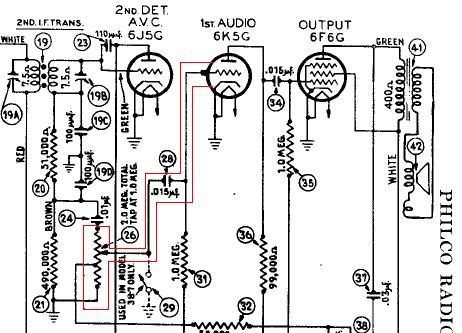
 voltage readings
Now with the 100W removed, I again applied power.  After warm up, I checked the voltages, recording the readings in a log book.

The rectifier voltage was now at ~290V, about 10% low.  Most other voltages were 10 to 20% low.

Audio Amplifier Check
A quick way to check out the audio amplifier is to introduce a signal at the input to the audio amplifier stage.  This should reproduce that signal at the speaker.  By touching the center tap of the volume control with a screwdriver, or just touching the cap on the 1st audio amplifier tube, a 60 Hz  signal is introduced, which should result in a loud hum at the speaker.

In this section of the schematic, the input to the audio section is outlined in red.

Although there was some hum from the speaker, you had to put your ear right at it to hear it, even at full volume.  Not good.

At this point I suspected either a bad tube, or two, or some other component failure.  Since I hadn't yet found a tube tester, and I had planned a full electrical rebuild in any event, that was my next step.

Further Inspection finds More Trouble 
In preparation for the rebuild, I again ran through both a visual inspection and an electrical check.  This time, though, I was much more methodical, carefully inspecting each and every part.  

The tuning capacitor has a slightly bent fin.  When the radio dial is below around 600Khz, the fins short out.  Careful work with a needle-nose pliers took care of that problem.

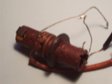
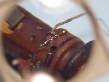
In walking through the schematic part-by-part, I discovered a disturbing problem.  The schematic shows that the antenna transformer for the broadcast band should have a resistance of around 0.1 ohm, but my meter showed that it was open-circuit.

Worriedly, I carefully unsoldered and removed the antenna transformer.
Here's the culprit!  This photo, taken through a magnifying glass, shows that the coil had somehow gotten a bit fried!  There should be a fine wire where the yellow arrow shows open air!
With patience, and luck, I was able to catch some solder on the remaining wire and bridge the gap with a strand of fine wire.

While reinstalling the transformer in the chassis, I recalled the shop keeper's promise that the radio had been working, but maybe just needed a tube.  Maybe in 1938 it was working, but never in the months the shop had it! 


[ Prev ] [ Next ]


Web Counter
Lilian Vernon
Copyright © 2004 look4000@verizon.net 
Last modified: November 01, 2008