|
| |
|
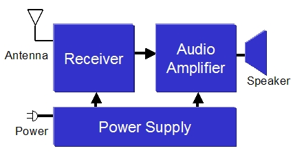
Basic Block Diagram
|
| There are far more
detailed tutorials available elsewhere (see references), but understanding
this simple block diagram is helpful in determining where problems
lie. I'll refer to this block diagram in the following sections as
well.
So here's my
attempt at a 30 second tutorial on how a radio operates:
-
The
power supply converts input power to usable voltages. Input
power is typically AC wall power (though battery operated (DC) and
combination AC/DC sets are common as well).
The power
supply contains a rectifier tube that converts AC to DC, and
electrolytic capacitors that smooth the resulting voltage. These
are the caps that are always trouble with age.
DC power
is supplied to the Receiver and Audio Amplifier sections.
-
The
receiver pulls in radio signals from the antenna and converts them to
audio signals, albeit at very low strength. The IF oscillator,
Detector, and IF Amplifier are within this stage.
-
The
Audio Amplifier takes the very weak audio signal from the Receiver,
and amplifies it, driving the speaker. Volume and tone controls
are also within this stage.
If
you can identify these three main areas of your schematic, then you'll be
in great shape to isolate issues and determine the health of each stage. |
[ Prev ] [ Next ]
| |
|